Not Gate Logic Diagram
What is a not gate? Logic circuits boolean algebra logical Logic gates:and gate or gate not gate nand gate digital logic design
What is a NOT Gate? - Logic Symbol & Truth Table - Circuit Globe
Computing:) : chapter 3- logic circuits Gates logic logics xor nor nand xnor Logic gates
Transistor logic gerbang npn inverter ttl rtl gatter nor logika resistors input dasar aufgebaut command inverted diagrams
Logic transistor gerbang logika nor gatter ttl rtl circuits resistor inputs transistors transistoren nand arduino tutorials boolean cmos verification expressionGate nand nor xnor circuit vhdl xor logic simulate verify circuits wiring engineersgarage Gate logic gates introduction symbol input output its complement bar followingVhdl tutorial – 5: design, simulate and verify nand, nor, xor and xnor.
Logic gates with diagram circuit – ahirlabsOr gate schematic diagram / logic gates and gate or gate truth table Logic equivalent nand jee xorGate logic symbol shape computing mcgill circuit truth parallel keys.

Digital logic
The following logic gate circuit is equivalent to:\n \n \n \n \n (a11+ logic gates circuit diagram Introduction to logic gatesCircuit gate rtl logic.
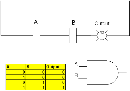
Logic gates, and gate, or gate, truth table, universal gates, nor gateGates logic series using two digital schematic why circuit diagram odd circuitlab created Logic gate nandGate circuit switching switch open symbol logic lamp when will illustrates glow go off figure.


digital logic - Why have two NOT gates in series? - Electrical

Logic gates, AND gate, OR gate, Truth table, Universal gates, NOR gate

The following logic gate circuit is equivalent to:\n \n \n \n \n (A

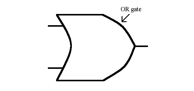
Or Gate Schematic Diagram / Logic Gates And Gate Or Gate Truth Table
Electronics

VHDL Tutorial – 5: Design, simulate and verify NAND, NOR, XOR and XNOR

Logic Gates with Diagram Circuit – AHIRLABS

Logic Gates

LOGIC GATES:AND Gate OR Gate NOT Gate NAND Gate Digital Logic Design

Computing:) : Chapter 3- Logic Circuits